
Types of Wireless Communication Systems:
- Television and Radio Broadcasting
- Satellite Communication
- Microwave Communication
- Radar Communication
- Mobile Telephone System (Cellular Communication)
- Global Positioning System (GPS)
- Infrared Communication
- WLAN (Wi-Fi)
- Bluetooth
- ZigBee
- Cordless Phones
- Radio Frequency Identification (RFID)
Applications of Wireless Communication Systems:
- Space research
- Defence and Military applications
- Telecommunications
- Wireless Power Transmission
- Internet of Things (IoT)
- Radar communication
- Artificial intelligence
- Intelligent Transport Systems
- Security systems
- Television remote control
- Cell phones
- Computer interface devices
- Asset tracking and Inventory management.
PRACTICE SESSIONS
1. Implement WLAN in your computer lab.
To setup a WLAN (Wireless Local Area Network) following equipments are required:
- A Wireless Wi-Fi Router with power adapter. (D-Link or TPLink)
- 2 or 3 Laptop / Desktop computers with Wireless network Dongle / Wi-Fi card enabled.
Procedure to connect to a wireless network:
- Switch ON the Wireless Router and all the computers to be networked.
- On each computers to be connected, select the Network icon on the taskbar.

- Choose the Wi-Fi network name of your Wi-Fi Router, then select Connect.
- Type the network password, and then select Next.
- Choose Yes or No, depending on the type of network you’re connecting to and if you want your PC to be discoverable by other PCs and devices on the network.
Set the Computer Name to easily identify the computer on the network:

To enable network discovery through Control Panel, use these steps:
- Open Control Panel.
- Click on Network and Internet.
- Click on Network and Sharing Center.
- Click the Change advanced sharing settings option from the left pane.
- Expand the Private network profile.
- Under the “Network discovery” section, select the Turn on network discovery option.
- Under the “File and printer sharing” section, select the “Turn on file and printer sharing” option.
- Expand the All Networks tab.
- Under the “Password protected sharing” section, select the Turn off password protected sharing option.
- Click the Save changes button.
After you complete the steps, you should now be able to find other computers in the local network.
To share a file or folder in File Explorer, do one of the following:
- Right-click on a file or folder, select Give access to > Specific people.
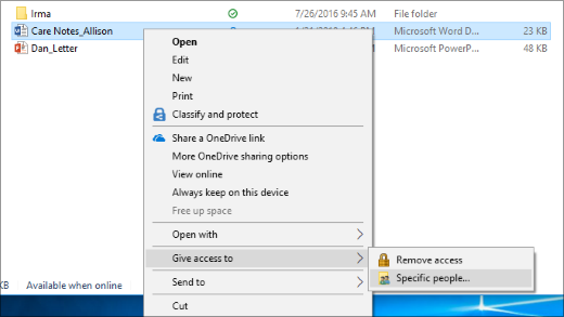
Or
- Select a file or folder, select the Share tab at the top of File Explorer, and then in the Share with section select Specific people.
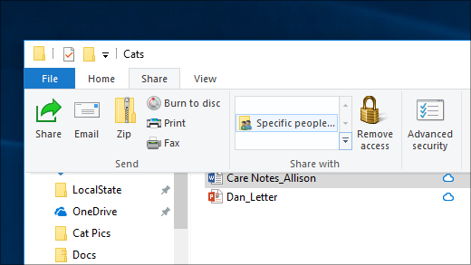
Select a user on the network to share the file or folder with, or select Everyone to give all network users access to the file.
2a. Conduct an experiment to connect PC to internet through Bluetooth access point of mobile and transfer a text file/image file/video file.
Procedure to connect PC to internet through Bluetooth access point of mobile:
- Turn on Bluetooth on your phone.
- Enable your phone to be discoverable through Bluetooth. By default, this is not enabled.
- On your phone, go to Settings > More networks > Tethering and portable hotspot.
[Note: On different phones, you may also find the tethering option under the Mobile Data or Personal Hotspot section.]
- Enable the Bluetooth tethering option.
- On your PC, turn on Bluetooth and pair with your phone.
- On a Windows 10 PC, click the Start button > the Settings icon.
- Click Devices.
- Turn ON the Bluetooth.
- Click Add Bluetooth or other device.
- Click Bluetooth, then select your phone.
- Click Connect. And if you’re prompted to pair with your PC on your phone, tap Pair or Yes.
- It will be displayed as Paired on your computer.
Steps to send files from your Windows PC to your Android phone
- Turn on Bluetooth on your PC and pair with your phone.
- On your PC, select Start > Settings > Devices > Bluetooth & other devices.
- In Bluetooth & other devices settings, scroll down to Related Settings, select Send or receive files via Bluetooth.
- In Bluetooth File Transfer, select Send files and choose the phone you want to share to then hit Next.
- Select Browse to find the file or files to share, then select Open > Next to send it, then Finish.
- On the device you are sending the file to, confirm that you want to accept the file.
For Android phones, the transferred files will appear in the Bluetooth folder of your device. You can access it by using the Files by Google app and look for the Bluetooth folder under your device name (e.g., Pixel 4XL). You can also find files received via Bluetooth in your phone’s Bluetooth settings > Connection preferences > Files received via Bluetooth. However, this list will get cleared out when you turn off Bluetooth or unpair your phone.
Steps to send files from your Android Phone to your Windows PC
- Turn on Bluetooth on your PC and pair with your phone.
- On your PC, select Start > Settings > Devices > Bluetooth & other devices.
- In Bluetooth & other devices settings, scroll down to Related Settings, select Send or receive files via Bluetooth.
- In Bluetooth File Transfer, select Receive files.
- On your phone, select the file(s) you want to send and hit the Share icon and select Bluetooth as the share option. Pick your Windows PC in the Choose Bluetooth Device screen.
- On your PC, the Save the received file options will now come up in the Bluetooth File Transfer window. Select the location where you want to save the file to and hit Finish.
2b. Interface RFID reader for any application using Arduino controller
EM-18 RFID Reader Module:
The EM-18 RFID Reader module operates at 125kHz. The Reader module comes with an on-chip antenna and can be powered up with a 5V power supply.
Typical Applications of RFID reader:
- e-Payment
- e-Toll Road Pricing
- e-Ticketing for Events
- e-Ticketing for Public Transport
- Access Control
- PC Access
- Authentication
EM-18 RFID Reader PIN DIAGRAM:

Interfacing EM18 Module with Arduino UNO (Circuit diagram):

ARDUINO code to read RFID TAG ID and print it on SERIAL MONITOR:

Procedure:
- Connect the ARDUINO board to the PC and upload the code using ARDUINO IDE tool.
- Make the circuit connection as per the circuit diagram.
- Open the Serial Monitor on ARDUINO IDE.
- On Serial Monitor “Scan RFID Tag!” message will be displayed.
- Show the RFID card/tag to the reader within the reading distance and the card number will be printed on Serial Monitor.
3. Video demonstration & documentation on working of
3a. Two cavity klystron.
3b. Reflex klystron.
Diagram of a two-cavity klystron, used as an amplifier and RF signal source at microwave frequencies, and also as an oscillator.

400 kW klystron used for spacecraft communication at the Canberra Deep Space Communications Complex.

More reading …
https://www.britannica.com/technology/electron-tube/Common-tubes-and-their-applications
3. Video demonstration & documentation on working of
3c. Magnetron.
3d. TWT.
Typical elements of a magnetron.

Elements of the traveling-wave tube (TWT).

4a. Study and measure the characteristics of pulse from signal generator using a CRO.

Basic Pulse Characteristics:
Rise Time and Fall Time:
Both rise and fall times are measured between the 10% and 90% points of the static voltage levels before and after the transition (20% and 80% points are sometimes used as alternatives).
Pulse Width:
Pulse width is the time between the leading and trailing edges of a pulse.
IEEE Standard Pulse Terms and Definitions:

| Term | Definition |
|---|---|
| Base Line | The two portions of a pulse waveform which represent the first nominal state from which a pulse departs and to which it ultimately returns. |
| Top Line | The portion of a pulse waveform which represents the second nominal state of a pulse. |
| First Transition | The major transition of a pulse waveform between the base line and the top line (commonly called the rising edge). |
| Last Transition | The major transition of a pulse waveform between the top of the pulse and the base line. (commonly called the falling edge). |
| Proximal Line | A magnitude reference line located near the base of a pulse at a specified percentage (normally 10%) of pulse magnitude. |
| Distal Line | A magnitude reference line located near the top of a pulse at a specified percentage (normally 90%) of pulse magnitude. |
| Mesial Line | A magnitude reference line located in the middle of a pulse at a specified percentage (normally 50%) of pulse magnitude. |
Wiring diagram:

Tabular Column:

Procedure:
- Connect the equipment as per the wiring diagram.
- Select the Square ware signal in the signal generator.
- Adjust the required frequency and amplitude.
- Observe the corresponding signal on the CRO.
- Note down the amplitude and time of the signal.
- Repeat the above steps for different frequency and amplitude.
4b. Conduct an experiment to use a smart phone as CCTV camera (or a CCTV camera) and connect it to another mobile to view the camera feed.

AlfredCamera helps to turn your mobile device or computer into a security camera, and you only need at least two of them to set up your security systems. AlfredCamera is available for free in the App Store and Google Play Store.
Procedure to set up AlfredCamera on your mobile devices:
Step 1 – Prepare 2 mobile devices
Requirements:
- Device: Phones or tablets (Both devices are connected to a network or internet)
- Original OS: Android 5.0+ or iOS 10+
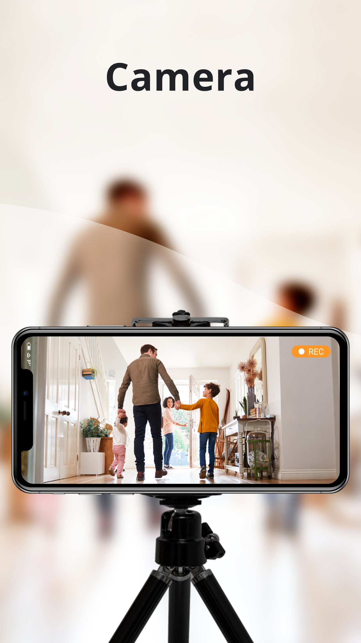
- One mobile phone as Camera to record motions (suggestion: your old phones)
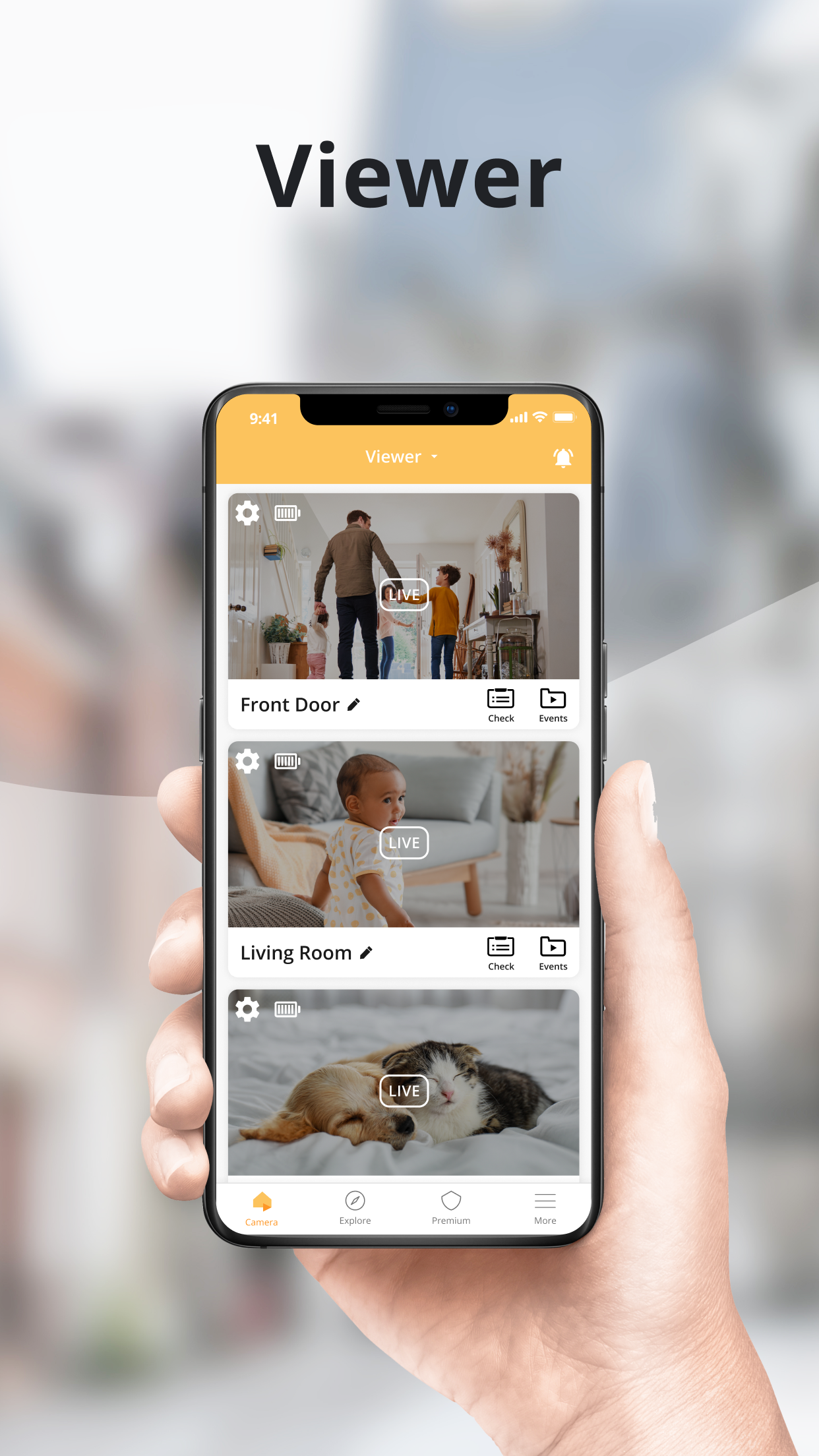
- One mobile phone as Viewer to check the feed from your camera device (suggestion: your daily phones)
Step 2 – Download Alfred app
Download Alfred app on your 2 devices from
- App Store (for iOS devices)
- Play Store (for Android devices)
Step 3 – Connect the 2 devices
Devices logged in with the same account will be connected to each other automatically. There are 2 options to connect your devices:
Option A : Log in on your 2 devices with the same account
- On the first device – Tap Continue with Google/Apple/Email to log in
- On the second device – Use the same login option to log in with the same account
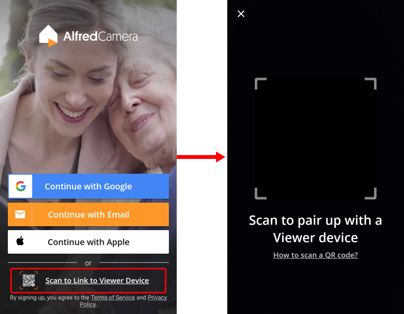
Option B : Scan the QR code on the Alfred app
- On the first device
- Login with your account.
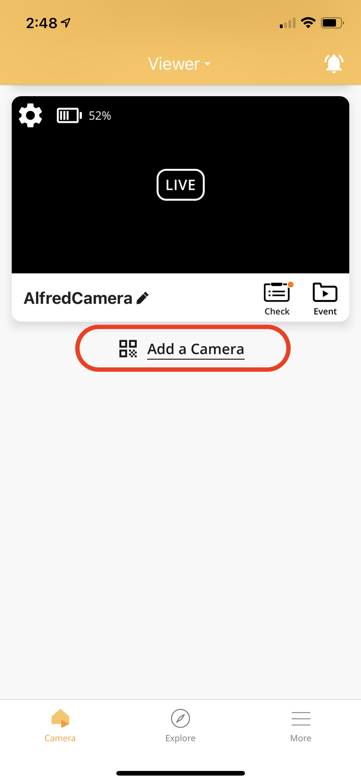
- Tap the Camera Tab
- Tap Add a Camera to generate a QR code
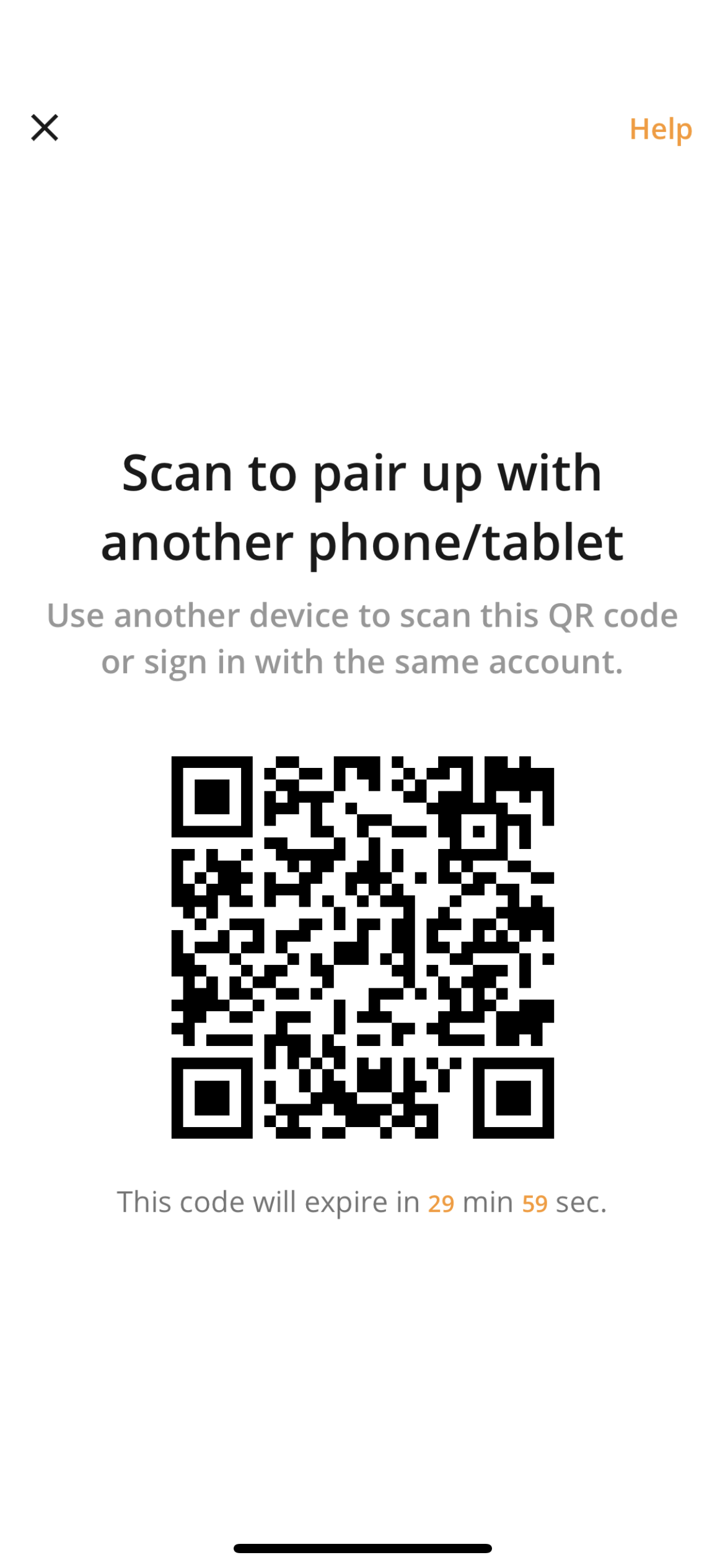
- On the second device
- Tap Scan to Link to Viewer Device to open an in-app scanner.
- Scan the QR code on the first device.
Step 4 – Make sure you have at least one Viewer & one Camera
Check the app’s toolbar on your 2 devices and make sure one is Viewer and another one is Camera. You can switch the device from Viewer to Camera and vice versa.
 .
. 
5a. Video demonstration and documentation to understand radar scanning and tracking systems.
5b.Video demonstration and documentation to understand the working of secondary surveillance radar.
5c. Interface Zigbee module for any application using Arduino controller.
Zigbee is a wireless communication protocol targeted for battery powered devices. It generally operates in the 2.4GHz range , and supports data ranges from 20 to 250 kbits/s.
The transmission distance t is 10 to 100 meters. In order to make Zigbee work with Arduino, we need to use the XBee module.
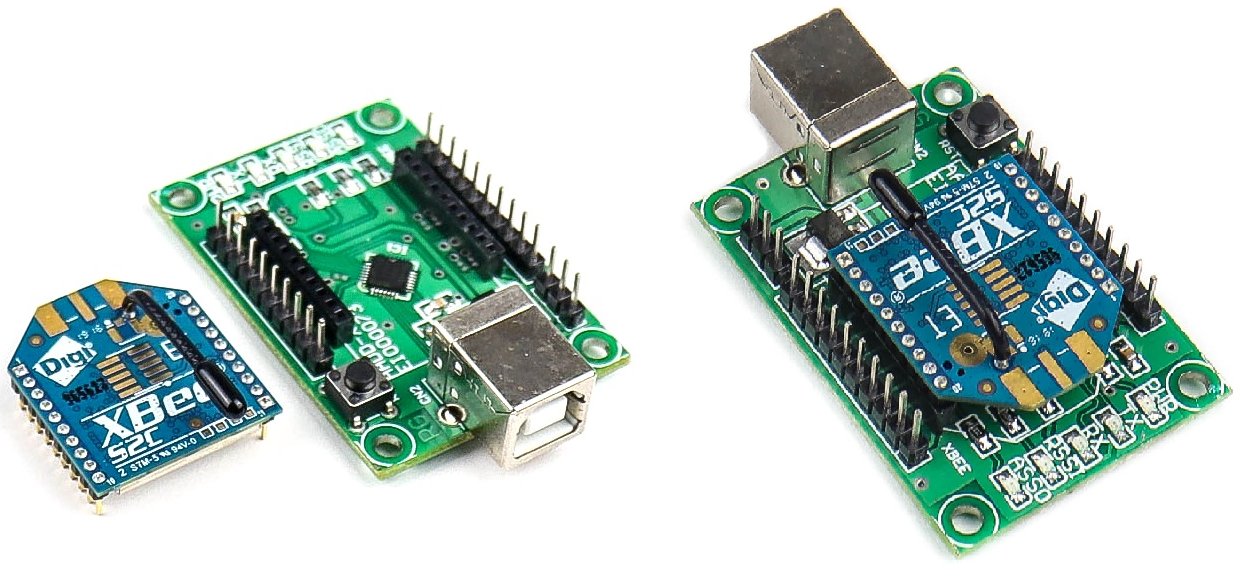
Digi XBee is the brand name of a popular family of form factor compatible wireless connectivity modules from Digi International.

Configure the ZigBee/Xbee modules:
1. XBee connection with USB adapter.
Place the XBee module on XBee USB adapter:
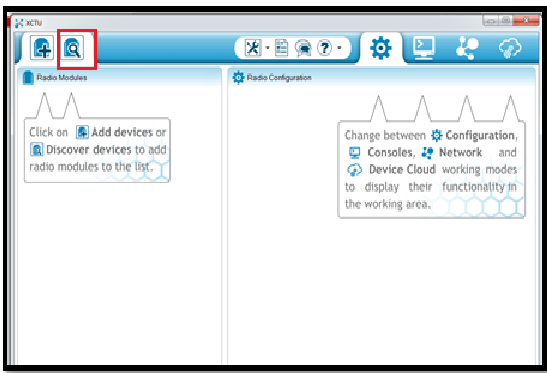
2. Download and Install XCTU software:
- Open XCTU software. Click on the search button of XCTU. It directs the XBee connected to the USB adapter. Let us start the configuration of the XBee module.
- Open the XCTU software& then click on the search on the top.
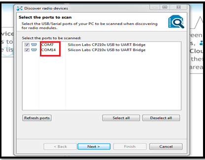
- To know the com port where radios are connected open the device manager and note down the com port. Select the ports and click on next.
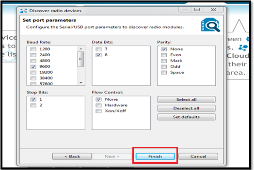
- Leave the port parameters to default. (i.e. 9600-8-N-1)
- 9600- Baud rate
- 8- Data bit
- Parity- None and 1- stop bit
And click on finish.
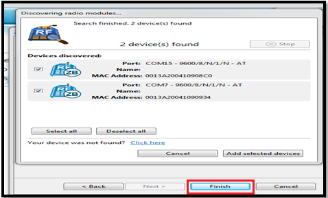
- The radios (XBees) are discovered by XCTU& click on Add selected device to see the XBee listed on the left side of the XCTU.
- Click on the First radio to load the setting.
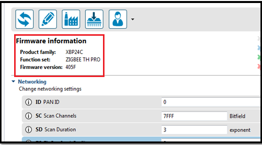
- To upgrade the latest firmware, click on the Upgrade Firmware and leave the function set to default and select the Newest version. Click on the finish to upgrade.

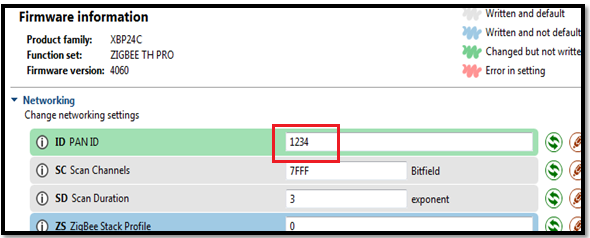
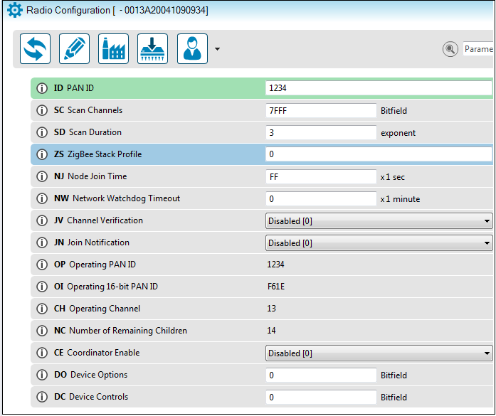
3. Now configure the first radio as COORDINATOR.
- First set Pan ID for your network. This can be any Hex value from 0 to FFFF. (Set it as 1234)
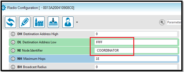
- To operate the Radio in the broadcast mode set the DL (Destination address) as FFFF. Type the name of the first radio in NI (Node Identifier). You can provide any name. Here the NI set as COORDINATOR.
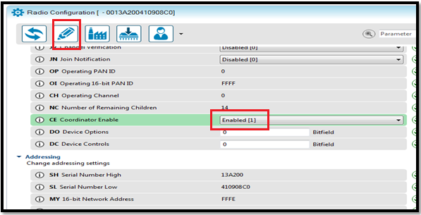
- To make the Radio as COORDINATOR, Set the CE parameter to Enable and click on the Write button (Pencil Icon) to save the information.
4. Now click on the second radio and configure this as ROUTER.
- Enter the Pan Id as 1234 which is the same as COORDINATOR. Set the JV channel Verification to enable so that it joins the COORDINATOR. Leave the CE to Disable and click on the Write to save the changes.
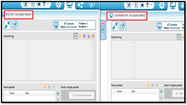
5. Communication between Coordinator and Router
The Radios are configured, now you can do the communication between the COORDINATOR and Router:
- Delete the second radio and click on the first one. This is the COORDINATOR and leave this XCTU window open and start another window of XCTU.
- Click on the search button of the second window of XCTU. Select the com port of the second radio. That is the ROUTER radio. Click on the router radio to load the settings.
6. Check the Output
Now the new window has a ROUTER and the old window has a COORDINATOR.
- Left side- ROUTER
- Right side- COORDINATOR
- Click on the Console terminal window of both radio and Serial OPEN button.
- Now you can type the message in the Console log window to see received by other radio. The transmitter message in BLUE and Received message in RED.
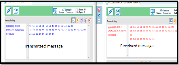
- This is Bidirectional communication.

Now using the XBee Sheild connect the Xbee Modules to arduino boards.

Connect One Xbee+Arduino board to one computer with arduino IDE and turn on Serial Monitor.
Connect another Xbee+Arduino board to another computer with arduino IDE and turn on Serial Monitor.
Type on one of the serial monitor and send it. You will be able to see the typed data on another computer.
6a. Study the features and working of different sections in a satellite communication trainer kit.
Satellite communication trainer kit MODEL : Scientech 2272A

Scientech 2272A Satellite Communication System provides an in-depth study of basic Satellite Communication system.
It consists of Uplink Transmitter, Satellite Link and Downlink Receiver. The Satellite can be placed at an elevated, position if needed. The Satellite Transponder receives signal from Uplink Transmitter and retransmits at different frequencies to a Downlink Receiver. The Uplink and Downlink frequencies are selectable and can have variety of signals such as Video, Audio, Voice, Tone, Data and Telemetry (Temperature and Light intensity).
Features:
- Simultaneous communication of three different signals.
- Communicate Audio, Video, Digital data, PC data, Tone, Voice, function generator waveforms etc.
- 2.4GHz Band PLL microwave operation.
- Communication of external broad band digital signal.
- Choice of different transmitting and receiving frequencies.
- Built-in Speaker and Microphone for Voice and Audio link.
- Remote detection of Light intensity and environment temperature.
- Detachable Dish Antenna at each station.
- USB port for PC communication.
Technical Specification:
Uplink Transmitter:
- Transmitter with selectable frequency conversion
- 2450-2468 MHz up-linking selectable frequencies
- Wide band RF amplifier. No manual matching required.
- 16 MHz Bandwidth
- Frequency select switch and LED indication.
- FM Modulation of Audio and Video.
- Coverage area 3.5meter Indoor and 10meter outdoor
- Transmit Audio, Video, Digital data, PC data, Tone, Voice, function generator waveforms etc.
- Separate section for telemetry operation.
Inbuilt Tone Generator:
- Frequency: 100Hz to 1 KHz.
- Amplitude: 0V to 1Vpp.
- Separate terminals provided for different inputs.
- Power Supply: 230 V AC ±10 %, 50/60 Hz
Satellite Link:
- Transponder with selectable Uplink and downlinks frequency conversion.
- Light and Temperature sensors for telemetry operations.
- Delay knob provided for simulated Transition delay experiment.
- Optional Solar power supply for Transponder Unit.
- Detachable Dish Antennas.
- Power Supply: 230 V AC ±10 %, 50/60 Hz
Downlink Receiver:
- Receiver with selectable frequency conversion.
- Receives and demodulate three signals simultaneously.
- Built in speaker for audio and video output.
- Detachable Dish Antenna.
- Power Supply: 230 V AC ±10 %, 50/60 Hz
6b.Conduct an experiment to Transmit & Receive three separate Signals (Audio, Video, and Tone/ Voice) simultaneously through satellite link and perform Link Fail Operations using satellite communication trainer kit.
Procedure:
Setting at Uplink Transmitter:
- Set the “Channel A” to ‘Video’ mode using the ‘Channel Select A’ key, so as to transmit video signals from Uplink Transmitter. The video signals are transmitted through ‘Video’ channel of the transmitter. Similarly set the “Channel B” to ‘Tone’ mode using the ‘Channel Select B’ key, so as to transmit tone signal from Uplink Transmitter. The ‘Tone’ signal is transmitted through ‘Audio II’ channel of the transmitter.
- Connect the Audio/Video signal at the input socket provided on the Uplink Transmitter, Video at video input and audio at Audio-I input.


Setting at Satellite Transponder:
- Keep the toggle switch to ‘Telemetry off’ position provided at Satellite Transponder unit.

Setting at Downlink Receiver:
- Now set the “Channel A” to ‘Video’ mode using the ‘Channel Select A’ key, so as to receive video signals from Uplink Transmitter. The video signals are received through ‘Video’ channel of the receiver. Similarly Now set the ‘Channel B’ to ‘Speaker’ mode using ‘Channel Select B key, so as to hear the tone signal. The Tone signal is switched to Speaker of Receiver.

- Connect TV monitor to the Audio/Video output of Downlink Receiver. (Video from Video Output, audio from Audio I output) Set TV in AV Mode.

- The TV monitor will display video and audio signal that you have connected to Uplink Transmitter input.

- Also the tone signal can be heard in the speaker of receiver.
- Try link fail by using Transponder “OFF”.
7a.Find the delay between Uplink transmitter and Downlink receiver during data transmission using satellite communication trainer kit.
Setting at Uplink Transmitter:
- Set the “Channel A” to ‘Data’ mode using the ‘Channel Select A’ key, so as to transmit data signals from Uplink Transmitter. The data signals are transmitted through ‘Video’ channel of the transmitter.
- Connect the DSO CHI (Digital Storage Oscilloscope Channel 1) to Data Generator test point.
Setting at Satellite Transponder:
- Keep the toggle switch to ‘Telemetry On’ position provided at Satellite Transponder unit.

Setting at Downlink Receiver:
- Now set the “Channel A” to ‘Data’ mode using the ‘Channel Select A’ key, so as to receive data signals from Uplink Transmitter. The data signals are received through ‘Video’ channel of the receiver.
- Connect the DSO CHII (Digital Storage Oscilloscope Channel 2) to “Received Data” section and observe the data.
- The recommended DSO settings are as follows:
- Adjust the Time/Div knob at 50ms.
- Adjust Volt/Div. Knob at 2V.
- Set appropriate trigger level, so that the signal becomes stable on screen.
- Select Acquisition mode to ‘Normal’ position
- Select Display ‘Persist’ to ‘Off’ position.
- Now gradually rotate the ‘Delay Adjust’ knob and observe the changes in the delay between the transmitted and received data.


8a.Video demonstration and documentation on ‘Working of GPS System’.
8b.Video demonstration and documentation on ‘Working of Satellite TV’.
8c.Conduct an experiment to tabulate latitude, longitude, Plus codes of different locations using a GPS receiver in mobile phone and learn sharing of live locations.
Latitude and Longitude are the units that represent the coordinates at geographic coordinate system. Both latitude and longitude are measured in degrees.
Get the coordinates of a place (latitude, longitude):
- On your Android phone or tablet, open the Google Maps app
.
- Touch and hold an area of the map that isn’t labeled to drop a red pin.
- In the search box, you can find the coordinates.
Format of coordinates:
- 41.40338, 2.17403 (latitude, longitude)
Tips:
- List your latitude coordinates before longitude coordinates.
- Check that the first number in your latitude coordinate is between -90 and 90.
- Check that the first number in your longitude coordinate is between -180 and 180.

Plus code:
Plus code is a feature introduced by Google on Google Maps App in 2018. This works even if you are offline since it does not rely of internet connectivity. Plus Codes work similar to street addresses. They can help you get and use a simple digital address. They can also help you define a specific location for a conventional address.
You can use Plus Codes to identify a specific location to receive deliveries, access emergency and social services, or direct people to a location. Since the codes are simple, you can easily share them with others.
Plus Codes are based on latitude and longitude. They use a simple grid system and a set of 20 alphanumeric characters. The character list purposely excludes easy to confuse characters like “1” or “l.”
Here’s an example of a Plus Code: JJXX+HR8, Seattle.
Find & share your current location’s Plus Code:
- On your Android phone or tablet, open the Google Maps app
- Tap the blue dot that shows your location.
- A blue screen will open with the Plus Code for your current location. For example:
JJXX+HR8, Seattle. - To copy a location’s code, tap the Plus Code.
- To share the location, paste the Plus Code into your email or messaging app, just as you would do for a traditional address.
If you’re offline, you might find a global Plus Code without a town or city name. Instead, an area code is added to the beginning of the Plus Code, like 9C5M8QQ7+V8.
9.Video demonstration and documentation of TV Set top box repair.
10.Understand the working of different sections in a mobile phone.

Workshop on Mobile phone servicing :
Build an IoT based simple real time application using Arduino controller and prepare a report.
NodeMCU is a low-cost open source IoT platform. It initially included firmware which runs on the ESP8266 Wi-Fi SoC (System on Chip) from Espressif Systems. NodeMCU is an open source firmware for which open source prototyping board designs are available. The name “NodeMCU” combines “node” and “MCU” (micro-controller unit).
ESP8266 NodeMCU V3:
https://www.electronicscomp.com/nodemcu-esp8266-wifi-development-board

ESP8266 NodeMCU V3 Pinout:
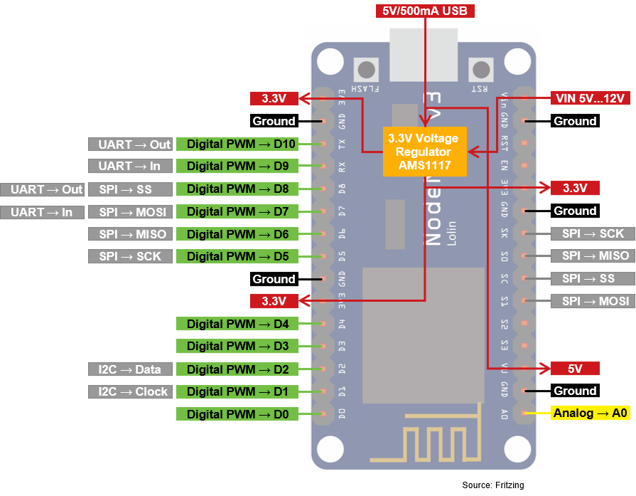
The ESP8266 NodeMCU V3, produced by Lolin.
Flash your Code on the ESP8266 NodeMCU: (Needs to be done only once on new ESP)
You can create your program script with the Arduino IDE and use the Arduino IDE to flash your code to the ESP8266 NodeMCU. There is only a small change in the Arduino IDE that is described in the following steps:
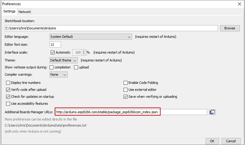
- In the Arduino IDE menu click on File → Preferences
- Insert the following URL in the field “Additional Boards Manager URLs:”:
http://arduino.esp8266.com/stable/package_esp8266com_index.json
The following picture shows the result in the preferences menu.
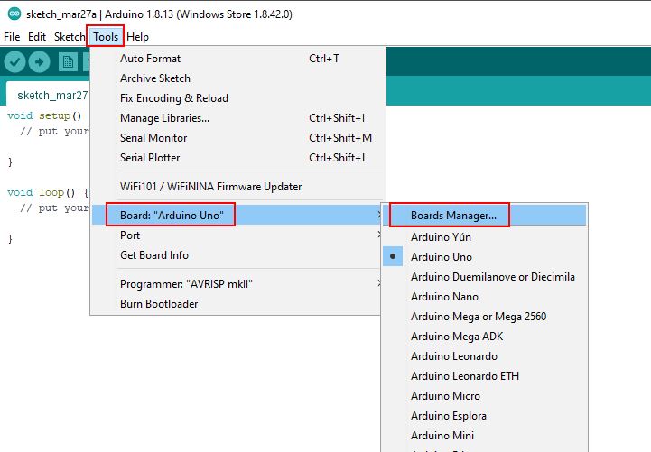
The second step is to install the necessary packages for the ESP8266 module:
- Click in the Arduino IDE on Tools → Board → Board Manager.
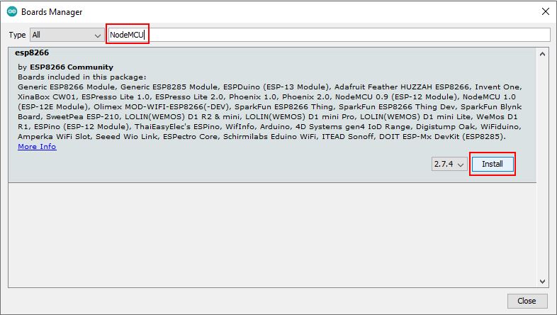
- Now search for NodeMCU and you will find the esp8266 by ESP8266 Community. Install the latest version of the board.
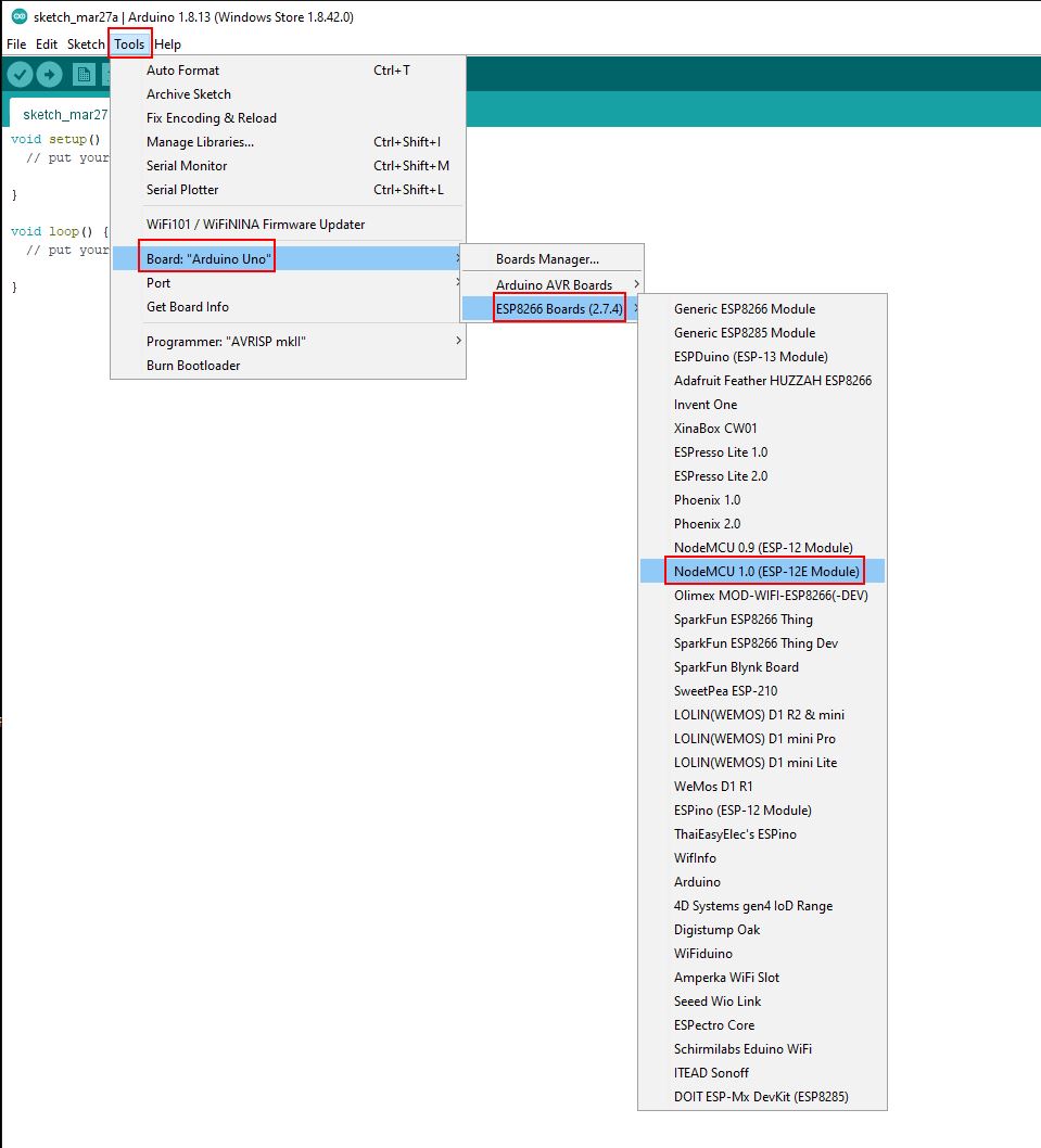
After the installation you can select the ESP8266 NodeMCU that has the name “NodeMCU 1.0 (ESP-12E Module)” under Tools → Board.
- https://thingspeak.com/
- 231 IoT projects ~ create.arduino.cc
- 200 IoT Projects for Engineering Students
- IoT Project Ideas for Engineers ~ Electronics for You
References:
- Pulse measurements
- Internet of Things A Hands-On Approach by Arshdeep Bahga, Vijay Madisetti
- Understanding of Satellite Communication : Scientech 2272A Product Tutorial (Manual)
- https://www.electronicshub.org/wireless-communication-introduction-types-applications/
