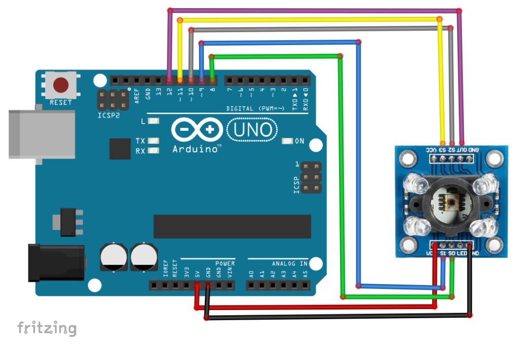
Wiring diagram:
Code for testing:
#define s0 8       //Module pins wiring
#define s1 9
#define s2 10
#define s3 11
#define out 12

int data=0;        //This is where we're going to stock our values

void setup()
{
   pinMode(s0,OUTPUT);    //pin modes
   pinMode(s1,OUTPUT);
   pinMode(s2,OUTPUT);
   pinMode(s3,OUTPUT);
   pinMode(out,INPUT);

   Serial.begin(9600);   //intialize the serial monitor baud rate

   digitalWrite(s0,HIGH); //Putting S0/S1 on HIGH/HIGH levels means the output frequency scalling is at 100% (recommended)
   digitalWrite(s1,HIGH); //LOW/LOW is off HIGH/LOW is 20% and LOW/HIGH is  2%

}

void loop()                  //Every 2s we select a photodiodes set and read its data
{

   digitalWrite(s2,LOW);        //S2/S3 levels define which set of photodiodes we are using LOW/LOW is for RED LOW/HIGH is for Blue and HIGH/HIGH is for green
   digitalWrite(s3,LOW);
   Serial.print("Red value= ");
   GetData();                   //Executing GetData function to get the value

   digitalWrite(s2,LOW);
   digitalWrite(s3,HIGH);
   Serial.print("Blue value= ");
   GetData();

   digitalWrite(s2,HIGH);
   digitalWrite(s3,HIGH);
   Serial.print("Green value= ");
   GetData();

   Serial.println();

   delay(2000);
}

void GetData(){
   data=pulseIn(out,LOW);       //here we wait until "out" go LOW, we start measuring the duration and stops when "out" is HIGH again
   Serial.print(data);          //it's a time duration measured, which is related to frequency as the sensor gives a frequency depending on the color
   Serial.print("\t");          //The higher the frequency the lower the duration
   delay(20);
}
Code for color recognition:
#define s0 8        //Module pins wiring
#define s1 9
#define s2 10
#define s3 11
#define out 12

int Red=0, Blue=0, Green=0;  //RGB values

void setup()
{
   pinMode(s0,OUTPUT);    //pin modes
   pinMode(s1,OUTPUT);
   pinMode(s2,OUTPUT);
   pinMode(s3,OUTPUT);
   pinMode(out,INPUT);

   Serial.begin(9600);   //intialize the serial monitor baud rate

   digitalWrite(s0,HIGH); //Putting S0/S1 on HIGH/HIGH levels means the output frequency scalling is at 100% (recommended)
   digitalWrite(s1,HIGH); //LOW/LOW is off HIGH/LOW is 20% and LOW/HIGH is  2%

}

void loop(){

  GetColors();  //Execute the GetColors function to get the value of each RGB color

  if (Red <=15 && Green <=15 && Blue <=15) //If the values are low it's likely the white color (all the colors are present)
      Serial.println("White");

  else if (Red<Blue && Red<=Green && Red<23) //if Red value is the lowest one and smaller thant 23 it's likely Red
      Serial.println("Red");

  else if (Blue<Green && Blue<Red && Blue<20) //Same thing for Blue
      Serial.println("Blue");

  else if (Green<Red && Green-Blue<= 8)    //Green it was a little tricky, you can do it using the same method as above (the lowest), but here I used a reflective object
      Serial.println("Green");            //which means the blue value is very low too, so I decided to check the difference between green and blue and see if it's acceptable

  else
     Serial.println("Unknown");     //if the color is not recognized, you can add as many as you want


  delay(2000);                     //2s delay you can modify if you want


}


void GetColors()
{
  digitalWrite(s2, LOW);     //S2/S3 levels define which set of photodiodes we are using LOW/LOW is for RED LOW/HIGH is for Blue and HIGH/HIGH is for green
  digitalWrite(s3, LOW);
  Red = pulseIn(out, digitalRead(out) == HIGH ? LOW : HIGH);    //here we wait until "out" go LOW, we start measuring the duration and stops when "out" is HIGH again, if you have trouble with this expression check the bottom of the code
  delay(20);
  digitalWrite(s3, HIGH);    //Here we select the other color (set of photodiodes) and measure the other colors value using the same techinque
  Blue = pulseIn(out, digitalRead(out) == HIGH ? LOW : HIGH);
  delay(20);
  digitalWrite(s2, HIGH);
  Green = pulseIn(out, digitalRead(out) == HIGH ? LOW : HIGH);
  delay(20);
}
Sample output:

